Aristat User Manual
Aristat Controller Quad • Operational Manual • Version 0-1 (Web) • icecapsystems.com
Table of Contents
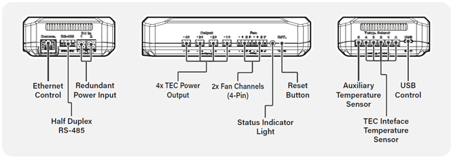
- Graphic Description
- Quick Start Guide
- Physical Connections
- Connecting Temperature Sensors
- Connecting Cascaded Thermo-electric Modules
- Driving 4-Pin Fan Devices
- Remote Controlling the Aristat Controller Quad
- Supplying DC Power to the Aristat Controller Quad
- Mounting Options
- Module LED
- Downloading and Installing the Aristat Software
- Using the Aristat Software
- Alerts and Errors List and Diagnostics
- Safety Features
- Maintenance and Care
- Warranty
General Safety Instructions
Read and understand all instructions before installing or using this device. Failure to follow safety precautions may result in damage to the device or connected equipment, or create a risk of fire or injury.
This device is not intended for life-support or safety-critical systems unless explicitly approved for such use.
Quick Start Guide
Identify your system requirements: Determine the desired set point temperature, estimated heat load, expected hot side temperature, and your cooling method (e.g. active heatsink or liquid cooling loop).
Choose the right thermoelectric stack: Select part numbers based on your system needs. Contact ICECAP Systems (info@icecapsystems.com) should you need guidance
Connect the components: Attach the temperature sensors to the appropriate points. Connect the correct number of thermoelectric stages.
Build the cooling system: Assemble the system based on your design and cooling requirements.
Connect the control module: Use USB or Ethernet to connect it to your PC.
Configure the system using ICECAP software: Open the software and set up the module as needed.
Operate the cooling system: Begin cooling either through the software or automatically at power-on.
Physical Connections
| Connection | Plug | Recommended Wire/ Cable |
|---|---|---|
| Ethernet | TIA-968-A RJ45 | CAT 5E or better |
| RS-485 | DIN 46228 pt 4 terminals | AWG 28 – AWG 24 |
| Redundant Power Inputs | MX-46992-0410 Housing with MX-5558T3L Crimp Contact | AWG 16; Stranded; Copper |
| TEC Power Outputs | DIN 46228 pt 4 terminals | AWG 28 – AWG 24 |
| Fan Channels | DIN 46228 pt 4 terminals | AWG 28 – AWG 24 |
| Temperature Sensors | DIN 46228 pt 4 terminals | AWG 28 – AWG 24 |
| USB Control | USB 2.0 over USB Type C |
Connecting Temperature Sensors
To ensure accurate operation, follow these steps to connect your temperature sensors correctly.
Choose temperature sensor type: The Aristat Controller Quad supports Type-T, Type-K, or two-wire PT-1000 Sensors.
Use only one sensor type across all channels. Do not mix sensor types. Select and prepare sensors: Use appropriate conductor size (refer to table in Physical Connections section).
Crimp appropriate ferrule for a secure connection (refer to table in Physical Connections section).
Limit cable Length (PT-1000 only): when using PT-1000 sensors, keep cable length under 5m to maintain reading accuracy.
Connect sensors in the appropriate sequence: Begin with the hottest sensor and connect it to channel 5. Proceed in descending temperature order by connecting cooler sensors to channel 4,3, 2 and 1.
Refer to the enclosure markings to identify the correct channel number and polarity.
Number of Stages
| 4 Stage | 3 Stage | 2 Stage | 1 Stage | |
|---|---|---|---|---|
| Temperature Sensor Channel | ||||
| Channel 5 | Hot Side Heat Sink | Hot Side Heat Sink | Hot Side Heat Sink | Hot Side Heat Sink |
| Channel 4 | Junction | Junction | Junction | Payload |
| Channel 3 | Junction | Junction | Payload | |
| Channel 2 | Junction | Payload | ||
| Channel 1 | Payload |
Connecting Cascaded Thermo-electric Modules
To ensure correct operation and minimize power losses, thermoelectric modules should be connected as outlined below.
Crimp appropriate ferrule for a secure connection (refer to table in Physical Connections section).
Keep cable length under 5 meters to minimize power losses along the cable.
Connect in descending order of output power, beginning with the highest Refer to table below for connection schemes from 1 stage up to 4 stages.
Connect the highest power module to channel 4.
Connect the remaining modules to channels 3, 2, and 1 in order of decreasing power.
Refer to the enclosure markings to identify the correct channel number and polarity
| 4 Stage | 3 Stage | 2 Stage | 1 Stage | |
|---|---|---|---|---|
| Channel 4 | Stage 4 | Stage 3 | Stage 2 | Stage 1 |
| Channel 3 | Stage 3 | Stage 2 | Stage 1 | |
| Channel 2 | Stage 2 | Stage 1 | ||
| Channel 1 | Stage 1 |
Driving 4-Pin Fan Devices
The Aristat Controller Quad includes two 12V fan outputs, designed primarily for 4-pin PWM fans, with optional speed control and tachometer feedback. These outputs may also serve as general-purpose 12V power supplies within specified limits.
The outputs share a combined maximum power of 96W. Ensure that the total power draw does not exceed this limit.
These outputs are intended for standard 4-pin PWM system fans offering both speed control and tachometer monitoring for each channel. They may also be used to control 4-pin liquid cooling pumps.
Crimp appropriate ferrule for a secure connection (refer to table in Physical Connections section).
Refer to the enclosure markings to identify the correct channel number and polarity.
Remote Controlling the Aristat Controller Quad
For remote control and telemetry, the module supports interface via either USB (USB-C connector) or Ethernet (RJ-45). In either case connection to a PC allows for configuration of the device through the host software.
Supplying DC Power to the Aristat Controller Quad
The Aristat Controller Quad features dual DC power inputs, allowing for redundant power supply configurations, such as incorporating a battery backup. Proper setup ensures uninterrupted operation and protection against power loss.
- Power can be supplied through two separate input channels.
- Input 1 is the primary power input
- Input 2 functions as a redundant power source
The connected power sources must operate within the absolute power range of the device. It is essential to verify that all power supplies meet the specifications before connection.
Automatic switchover behavior: The system gives priority to the primary input as long as its voltage remains above 21V.
If the primary input voltage drops below 21V, and the secondary input is connected and within range, the controller will automatically switch to the secondary source.
When the primary input voltage is restored above 21V, the controller will revert to it automatically.
Refer to the enclosure markings to identify the correct channel number and polarity.
Mounting Options
The Aristat Controller Quad supports multiple mounting methods to suit a variety of installation environments:
Desktop Use: The unit can be placed directly on a flat surface using the integrated rubber bumpers. This setup is suitable for test benches or temporary installations where vibration and movement are minimal.
DIN Rail Mounting: For panel or enclosure installations, the device can be mounted using the supplied DIN rail bracket. Secure the bracket to the unit using the included countersunk socket screws before snapping the assembly onto a standard 35mm DIN rail.
Direct Frame Mounting: Alternatively, the unit can be mounted directly to a custom frame or panel using the same two-screw mounting points used for the DIN bracket. Ensure the surface is rigid and flat.
Note: Regardless of mounting method, ensure the unit is installed in a position that allows adequate passive airflow for cooling. Do not obstruct ventilation areas or install the device in enclosed spaces without proper thermal management.
Module LED
The device’s onboard RGB LED reflects a number of states for quick feedback of the module’s status. The status LED will light up in different colours at different points in time, this section details the meaning of each colour.
| Indication | Description |
|---|---|
| 1 — Off | No power is supplied to the device |
| 2 — Temporary blinking green | The board has undergone a power cycle and has successfully performed startup. |
| 3 — Amber | Device is in standby and awaiting instructions |
| 4 — Green | Device operation has been initiated and powering TE stack to reach desired set point |
| 5 — Magenta | The user has initiated one of the system tests |
| 6 — Solid red | The device has encountered a fatal error or has stopped operation for safety reasons. Kindly refer to the error report available on the user software or manually reset the device. |
| 7 — Blinking red | The board has entered an error state. Perform a manual reset using the reset button situated on the front of the device. |
Downloading and Installing the Aristat Software
The software to setup and monitor the Aristat device can be downloaded from the ICECAP Systems website at https://icecapsystems.com/aristat. Follow the installation guide as instructed and launch the software upon completion.
Using the Aristat Software
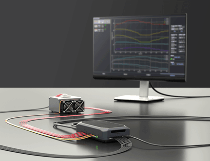
The Aristat control software enables a rapid and guided workflow to prepare, implement, and obtain telemetry for the integration and control of multiple multi-stage or single stage TECs. The software encourages the following workflow to set up one of the core module devices.
Discover
The discover tab is designed to find and initiate a communication link with any connected and responsive modules. This is possible either via USB and a virtual COM port, or via TCP with a fixed (but modifiable) static IP address. It is required to use USB communication for first-time setup.
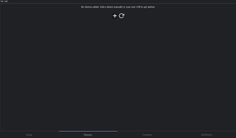
Once a module is connected via USB, either press the refresh button to automatically find available and connected devices (from the currently available COM ports), or alternatively manually add the corresponding module via the ‘+’ symbol.
A new entry corresponding to your new module should show up as shown below. Information about the device such as name, firmware version, model and licence type are provided, how it is connected and its status. Should the status be ‘OK’, and the indicator light green, the user may proceed to the next tab.

Should the user not wish to use this device now, they can remove this device from the list by means of the delete or bin button.
Configure
The configure tab provides controller customisation and configuration as well as setting required parameters for the user application. Navigation of this tab can be made using the left-hand navigation panel, which will display all currently connected devices whose drop down will reveal the configured cooling stacks as defined for that device.
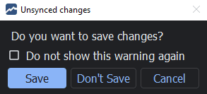
The settings displayed are fetched from the device upon connection and reflect the current device configuration. Should this not be the case, the ‘Sync from Device’ button under the left-hand navigation panel will fetch all the necessary configuration from the connected device selected. Should there be any changes in the configuration of the module, the software will indicate this through the following notification. The user may decide to discard the changes or apply these changes through the ‘Sync to Device’ button.

Module View
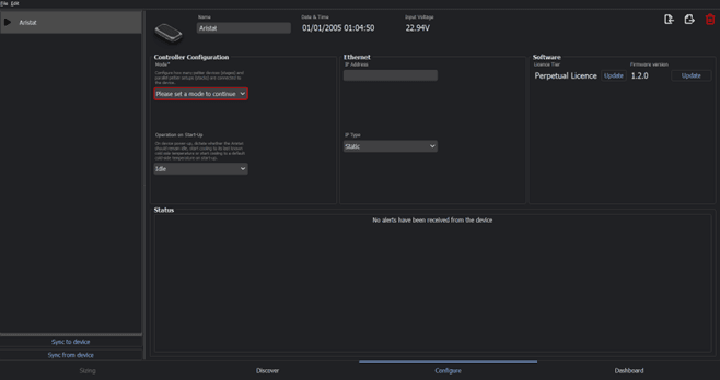
Once a module has been successfully discovered its name appear in the left-hand navigation panel. These parameters can be configured at any time. A number of sections are divided as follows:
Controller Configuration: this section is for critical device information required such as the type of thermoelectric stacks being driven, and the operation mode on start-up. The mode refers to the intended cooling configuration that will be used, which is dependent on the capabilities of the core module’s model. A number of options are provided for a given number of cooling stacks and number of stages. Selecting one of these options will display the selected number of thermoelectric stacks in the left hand panel.
The start-up type indicates to the device whether it shall start operating on power-on with a default profile, whether it will await user intervention through the software or whether it will assume the last known operating conditions.
These fields are compulsory.
Software: the Software section provides the user to customise and setup the ICECAP subscription for using advanced features of the Aristat, as well as the current firmware version and performing firmware updates of the device. Note that firmware updates can only be performed over a USB connection.
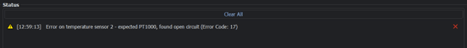
Status: this section will provide the user of any known errors or warnings notifications from the device.
Once the user is satisfied with these parameters, the ‘Sync to device’ button will save this configuration to the device, and the user may proceed to the stack configuration view from the left hand navigation panel.
Stack Configuration View
The stack configuration view is where any system parameters for individual stacks from the left-hand navigation panel should be configured. The right-hand side will display the thermoelectric stack, with the latest temperature readings for each temperature sensor as well as the current voltage and current being applied to each stage. The stack configuration view is further subdivided into 3 tabs as follows.
Config Tab
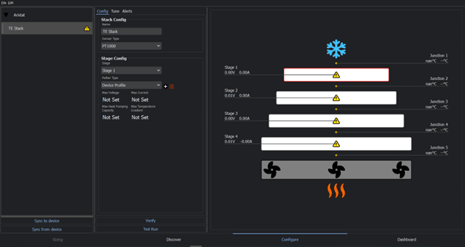
Use the ‘Stack Config’ panel to customise the display name of the current stack. It is important to also denote Pt1000, Type-K or Type-T thermocouples are being used.
Use the ‘Stage Config’ panel for the nominal operation of each thermoelectric device across each stage. For each stage, define a peltier type or part number to provide maximum ratings for each peltier device’s voltage, current, heat pumping capacity and temperature gradient according to the manufacturer’s datasheet.
According to the number of stages set by the operation mode, you may modify the nominal operation for each channel according to the thermoelectric device in the application.
Testing
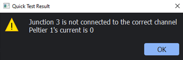
On connecting the stack, a Verification Test can be performed by means of the ‘Verify’ button to validate the electrical connections. This will ensure power is being delivered to the peltiers and the temperature sensors readings are sensible.
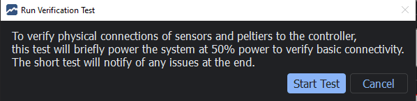
Should there be any problems detected by the software, the result of the quick test will provide a diagnosis, as in the example below.
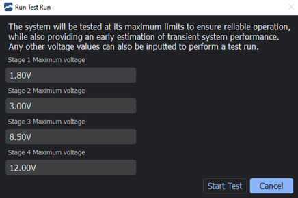
Once the user is satisfied with their electrical setup, the system limits can be better understood by the user by performing a Test Run. This is performed by setting each channel voltage according to user input to obtain an open loop performance of the system. The stress test can be monitored through the right-hand panel. The stress test will continue to run until it is manually halted.
Tune Tab
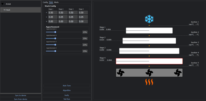
The tune tab provides configuration on the operation or control of the thermoelectric stack. Custom Proportional, Derivative and Integral parameters for each of the PID controllers that controls each stage respectively my be modified, or default values used. The temperature apportionment of each stage, that is the temperature difference created by each stage, may also be modified.
Depending on the subscription available to the device, the user may also opt to make use of the ICECAP Power Optimisation Algorithm.
Dashboard
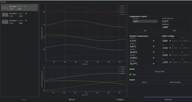
Lastly, the dashboard tab is designed to facilitate control and monitoring of the thermoelectric stacks across all devices during operation. Each individual stack is selectable on the left-hand panel, denoted by their display name and their respective device. Selecting the stack will display a live view on the left-hand side of the current temperature, voltage, current and power values. The status and performance of the thermoelectric stacks may be monitored here.
The upper plot will display the temperature readings for each junction in the stack, with the lower plot displaying voltages, currents, or powers. Readings may be hidden from the plots or shown from the panels on right hand side displaying current numerical values for each metric.
When ready, the Set Point for the desired object temperature can be inputted, before initiating control by means of Run. Operation may be stopped at any time by means of the Stop button.
Should the user wish to perform further analysis or obtain the data, they can make use of the Export, or right clicking on the plot itself, to .csv format. Start Recording will also start streaming readings to a .csv file for data logging purposes.
Safety Features
Aristat Controller Quad is equipped with multiple safety features designed to protect the device and connected systems during operation:
- Reverse Polarity Input Protection: Prevents damage if the input power is connected with reversed polarity.
- Overvoltage Input Protection: Protects the device by limiting or shutting down operation if the input voltage exceeds the maximum allowable level.
- Undervoltage Input Protection: Prevents operation when input voltage drops below the minimum threshold, ensuring stable and reliable system behavior.
- Output Voltage Limit (User-Configurable): Each output includes a configurable voltage limit to prevent excessive output voltage. This must be correctly set by the user based on system requirements.
- Overcurrent Protection (User-Configurable): Active current limiting is available on each output. The user must configure appropriate current limits for each channel to protect both the controller and any connected downstream devices.
Important: Output protection features (voltage and current limits) must be properly configured by the user. Incorrect configuration may lead to overheating, malfunction, or permanent damage to the controller and/or connected equipment.
These safety functions enhance system protection, but correct setup and commissioning are essential to ensure safe and reliable operation.
Maintenance and Care
To ensure reliable long-term operation of the Aristat Controller Quad, follow these general maintenance and care guidelines. All maintenance must be performed by qualified personnel. Always isolate the device from power before inspection.
- Periodic Inspection: Regularly inspect the unit and wiring for signs of wear, loose connections, or corrosion. Ensure terminals remain secure and undamaged.
- Dust and Debris: Keep the unit free of dust, dirt, and debris. Clean using a dry, anti-static brush or low-pressure compressed air. Do not use solvents or liquid cleaners.
- Environmental Conditions: Ensure the device operates within the environmental parameters specified in the datasheet (temperature, humidity, and vibration). Avoid exposure to corrosive substances or excessive moisture.
- Airflow and Cooling: Maintain adequate clearance around the device to support passive airflow cooling. Do not obstruct ventilation openings, and ensure that enclosure design allows heat dissipation.
- Firmware and Configuration: Periodically review firmware and configuration settings to confirm they meet system requirements. Update only as instructed by the manufacturer.
- Power Cycling: Minimize unnecessary power cycling. When required, shut down connected systems gracefully before disconnecting power.
- Mounting: Confirm that the unit remains firmly mounted, with all DIN rail or panel fasteners properly secured.
- Surge and Ground Protection: Use appropriate surge protection and ensure correct grounding to minimize the risk of electrical damage.
Warranty
The Aristat Controller Quad is covered by a limited warranty for a period of 24 months from the date of original purchase. This warranty applies to defects in materials and workmanship under normal use, installation, and environmental conditions as specified in the product datasheet.
This warranty is offered exclusively to business customers and applies only when the product is installed and operated according to the instructions provided in this manual and related technical documentation.
Coverage
The warranty covers:
- Functionality of the 4 primary output channels, 2 auxiliary outputs, 2 communication channels, and temperature sensing inputs.
- Performance within defined electrical, thermal, and environmental specifications.
Exclusions
The warranty does not cover:
- Damage resulting from improper installation, unauthorized modification, misuse, or operation outside specified limits.
- Normal wear, cosmetic damage, or damage from external causes such as power surges or environmental events.
How to Claim Warranty
If you believe your product is faulty under warranty:
- Contact the vendor from whom the product was originally purchased.
- Alternatively, you may open a support ticket directly with the manufacturer using the contact details below.
- A Return Material Authorization (RMA) may be required before returning any unit.
Limitation of Liability
The manufacturer’s liability is limited to the repair or replacement of the defective product. No liability is accepted for indirect or consequential damages.
Jurisdiction
This warranty is governed by and construed in accordance with the laws of Malta.